Disclaimer: the information provided on this page is given as is, i.e. without warranty that you will not break your system following it. Additionally, do not expect to get support and warranty from NETGEAR if this happens.
After my work on the Duo v2 and 102, NETGEAR was kind enough to provide me with a ReadyNAS 104 to play with. This page documents the work done in order to get mainline kernel support for the device and its various hardware parts, in order to be able to run a standard Debian and a grsec kernel on it. If you were interested in the RN102 but would have like more disk bays, then the 104 is the one you were waiting for.
The RN104 is very similar on many aspects to the RN102 (same ISL12057 RTC chips, same Marvell Armada 370 @1.2GHz, same amount of memory, same USB 3.0 controller, etc). The main differences are the following:
- 2 GbE interfaces instead of 1 on RN102
- 4 SATA bays (using a 88SE9215 SATA controller) instead of 2 on RN102
- A front 16x2 characters Winstar WH1602G LCD
For that reason, the additional work to get a working .dts file after the time already spent on RN102 was limited.
Here is the main table of contents for the page, with links to the various sections of the page.
- Changelog for this page
- Work in progress, i.e. TODO list
- Hardware specs
- Configuring alarm for poweroff and automatic reboot
- Configuring custom actions for buttons
Changelog i.e. work done
- June 2015: I found some time to document how alarm support can be used for poweroff and automatic poweron of the device. See the alarm section for details on how to Configure alarm for poweroff and automatic reboot.
- February 2015: I finally managed to have alarm support patches for ReadyNAS RN102, RN202 and RN2120 using the ISL12057 RTC chip accepted in upstream kernel v4.0 (1a67e256dbd8, 298ff0122ab1, fd71493d6797). This allows you to very simply install an alarm time, power off your NAS and see it reboot at the programmed value. cron being your friend, you can very simply program different behaviours for each day of the week.
- October 2014: Added a basic script to associate actions to power, reset and backup buttons.
- January 2014: After a lot of struggle due to an inactive RTC maintainer, Support for Intersil ISL12057 I2C RTC chip has been accepted usptream and will be available in 3.14 kernel. Alarm support is still missing though, i.e. you will not be able to wake-up the NAS with a mainline kernel at the moment. Thanks to Ezequiel Garcia, RN104 will be able to benefit from Armada 370 NAND controller support, i.e. instead of updating kernel from u-boot, it will possible from userland starting w/ 3.14. kernel.
- November 2013: It seems RN104 support will be in 3.13 in the end
- October 2013: RN104 received. First disassembly. Initial working .dts file written and pushed upstream for integration in 3.14 kernel. Created this page. Support for SATA led control added to .dts. Support for SATA disks power regulators added to .dts.
Work in progress, i.e. TODO list
-
Add nodes for NAND controller when support gets available upstream - Write (and push upstream) support for Winstar WH1602G LCD
-
Push ISL 12057 driver upstream -
Work on alarm support for ISL 12057 RTC chip -
Add GPIO regulators nodes to control SATA disk poweron/off based on presence. -
Add NXP PCA9554 iomuxer (I2C to GPIOs) nodes to .dts file to control SATA LEDs -
Write and submit initial .dts file
Hardware Specs
- Marvell SoC Armada 370 ARMv7 @1.2Ghz
- 128 MB Hynix H27U1G8F2BTR NAND Flash
- 512 MB RAM via 2x256 Hynix DDR3 @1333Mhz
- Intersil ISL12057 I2C bus RTC
- Fresco Logic FL1009 USB 3.0 xHCI Controller
- GMT G762 PWM Fan Controller
- Protechnic Electric Co MG9212YB-25 Fan
- Main daughter board (rear ports)
- Main board front buttons and LED
- Marvell 88SE9170 PCI-e dual- port 6Gbps SATA controller
- Marvell 88E1318 Gigabit Ethernet PHY
- Serial interface via 16550A UART
- CR2032 battery
- Marvell G47B
- Richtek RT8105
- Texas instruments TPS65251
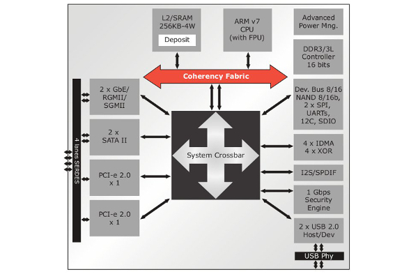
Marvell Armada 370
Like the ReadyNAS 102, the ReadyNAS 104 is powered by an (ARMv7-based) Marvell ARMADA 370 SoC. The CPU comes with a FPU and NX bit support. The SoC includes a 16-bit DDR3 memory interface, two ethernet MAC controllers (one routed on the 102), two DMA/XOR engines, a network security engine, two UART interfaces, thermal support, etc. The following Armada 370 SoC block diagrams (extracted from the product brief) provides an overview of supported functionalities:
The following excerpt (also fro the product brief) provides an expected typical use of the SoC in 2 bay NAS implementations:
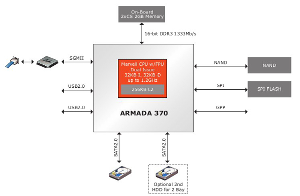
The ReadyNAS 102 uses this architecture with some additional hardware parts to support more functionalities (specific RTC with alarm support, USB 3.0, eSATA controller, etc)
Here is what /proc/cpuinfo reports for the CPU:
# cat /proc/cpuinfo
Processor	: Marvell PJ4Bv7 Processor rev 1 (v7l)
BogoMIPS	: 1196.85
Features	: swp half thumb fastmult vfp edsp vfpv3 vfpv3d16
CPU implementer	: 0x56
CPU architecture: 7
CPU variant	: 0x1
CPU part	: 0x581
CPU revision	: 1

Hardware	: Marvell Armada-370
Revision	: 0000
Serial		: 0000000000000000
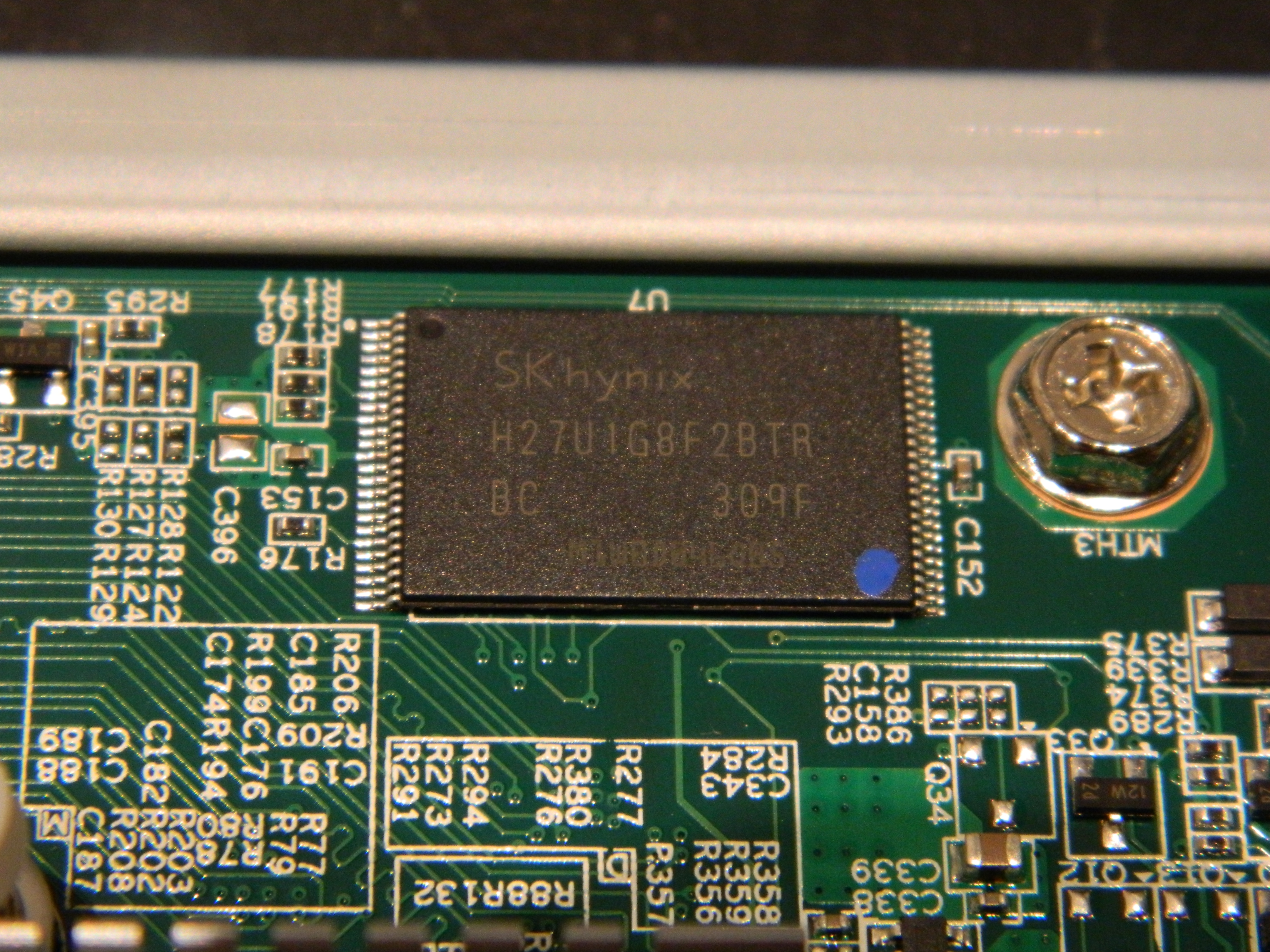
Hynix H27U1G8F2BTR
The ReadyNAS 104 comes with 128MB of NAND flash. This is provided by a single Hynix H27U1G8F2BTR chip, as depicted below. The same chip was used on the ReadyNAS Duo v2 and ReadyNAS Duo v2.
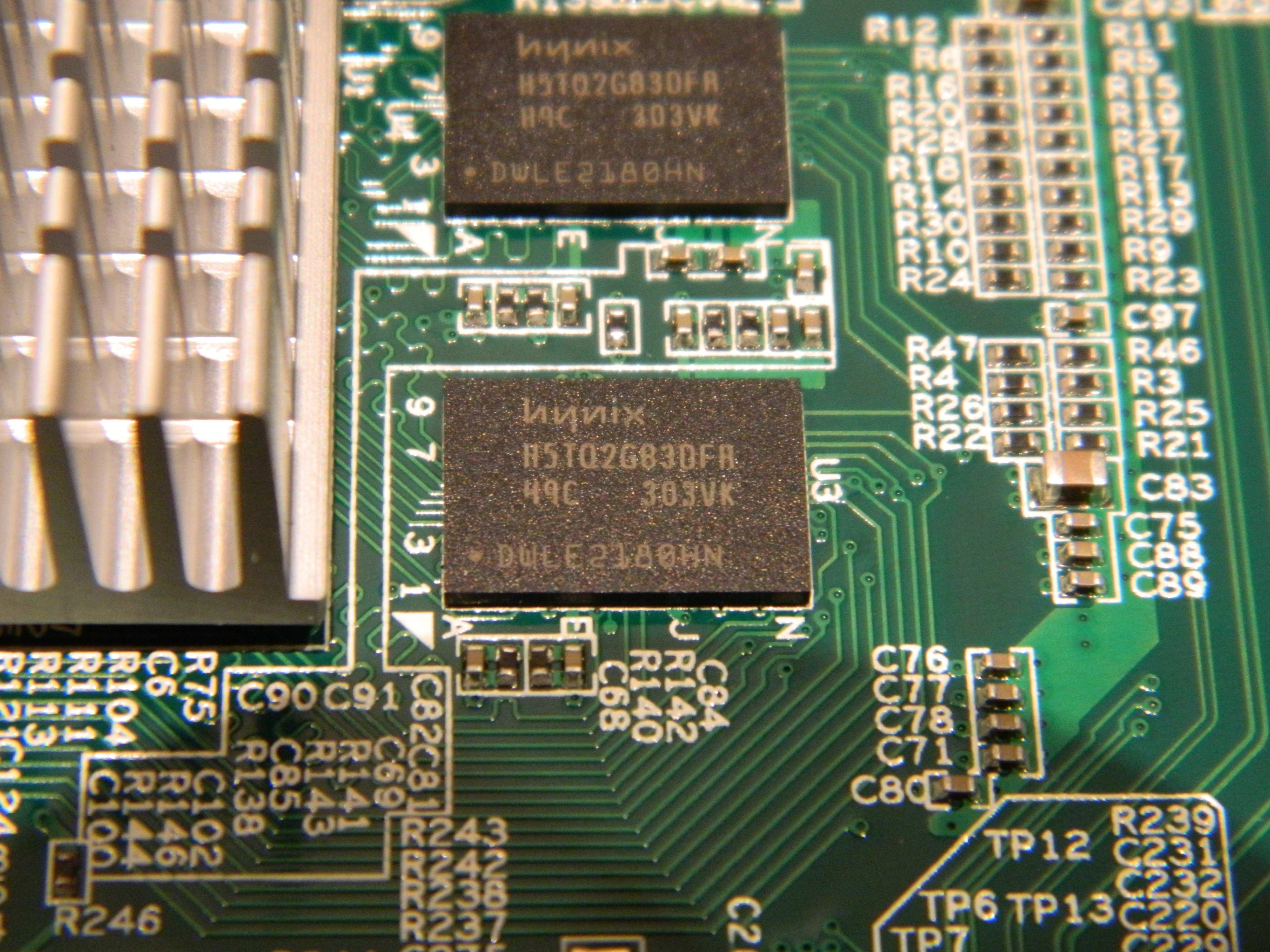
Hynix H5TQ2G83DFRH9C
The ReadyNAS 104 comes with 512MB of RAM connected to the SoC. This is provided by two soldered Hynix H5TQ2G83DFRH9C chips.
Intersil ISL12057 I2C bus RTC
The RaedyNAS 104 comes with an Intersil ISL12057 I2C bus RTC chip, as depicted below.
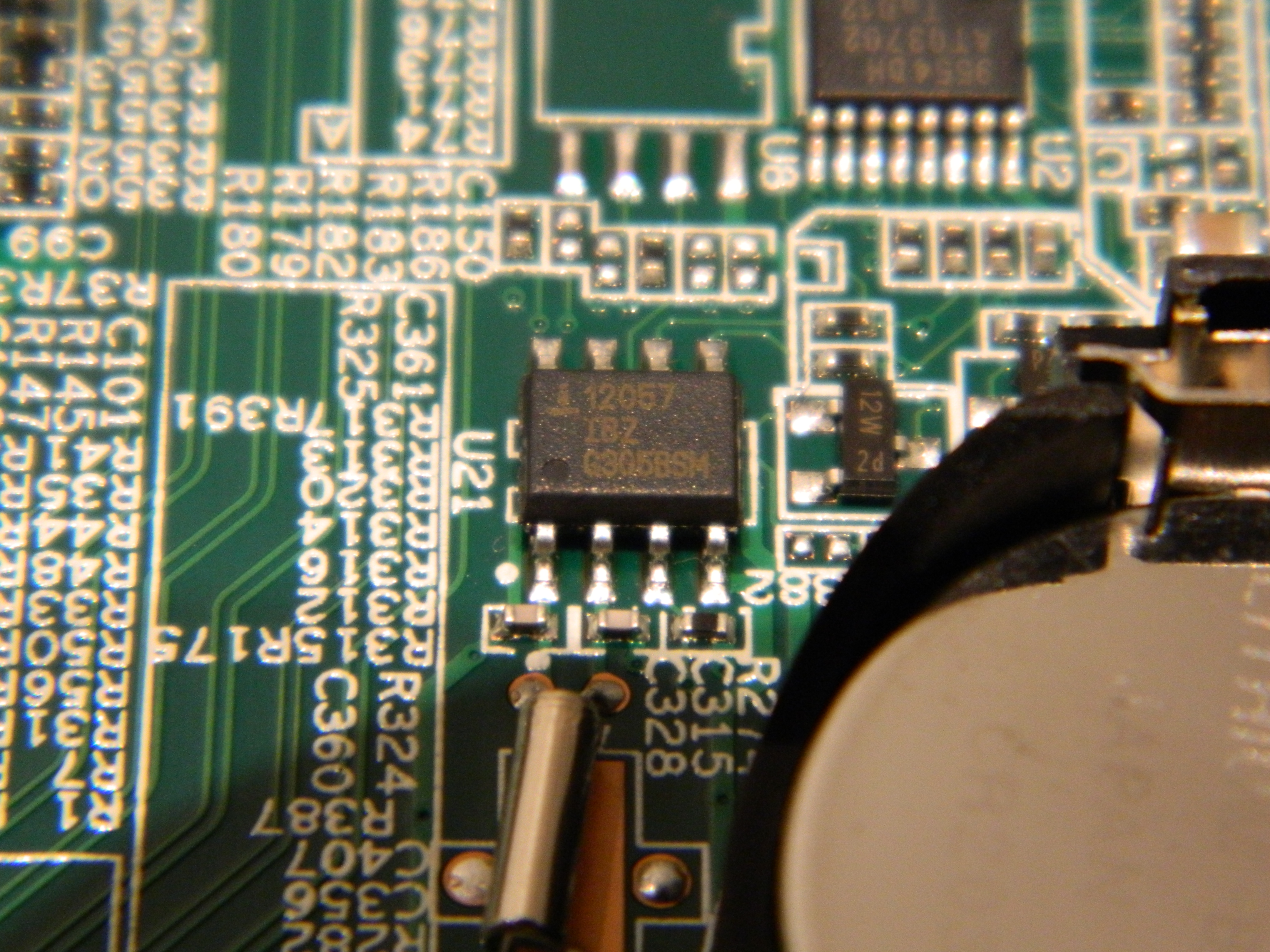
The Intersil ISL 12057 is a low power RTC and Alarm chip. A short patch (596 LoC) has been written by NETGEAR for the ReadyNAS 102 kernel (based on 3.0.56) but has never been pushed upstream. I decided to implement a driver for the chip based solely on existing ISL 12008 kernel driver and ISL12057 datasheet and push it upstream. The same chip is used on the RN104.
Fresco Logic FL1009 USB3.0/xHCI host controller
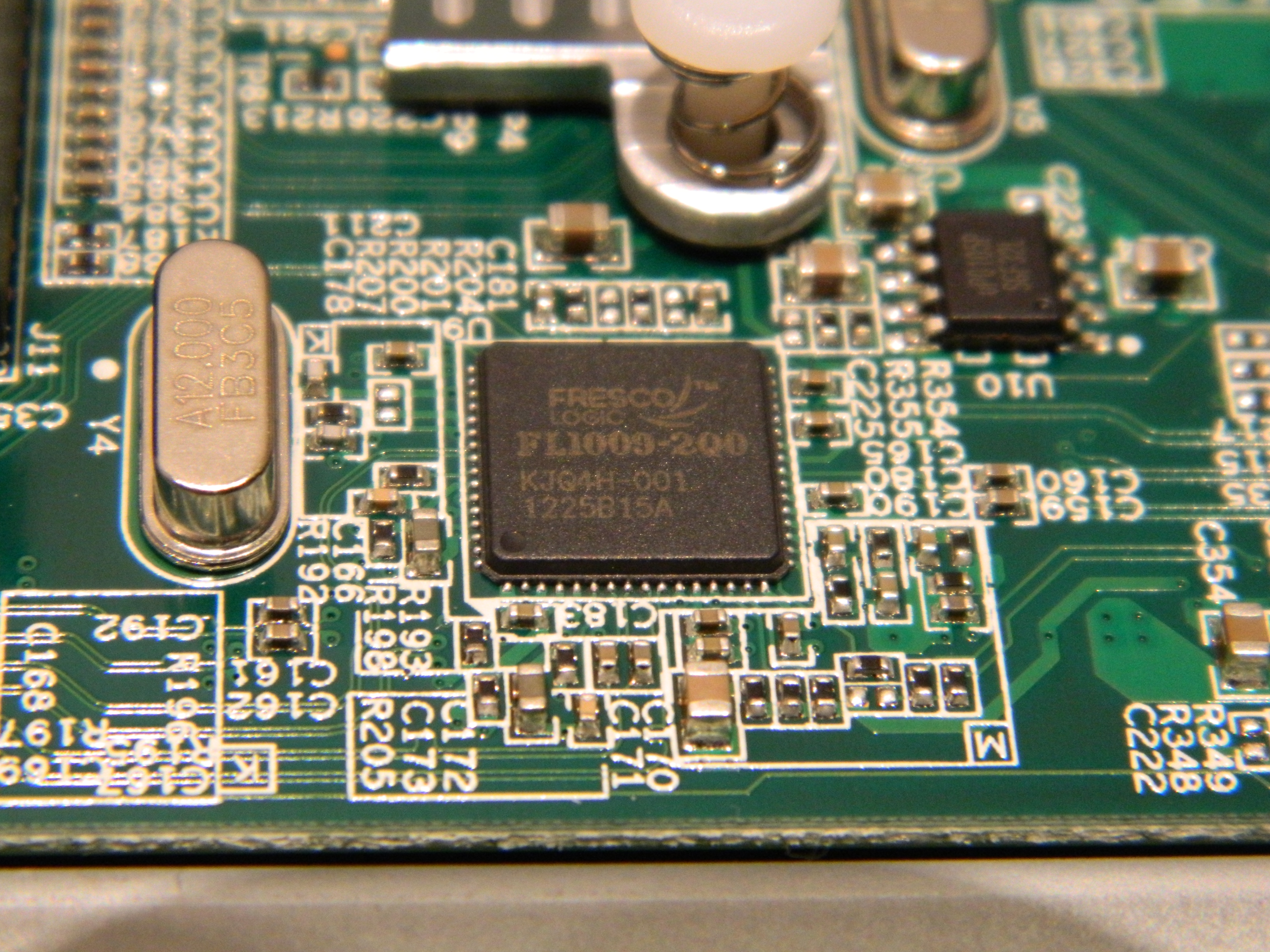
The USB3.0/xHCI controller used by the device is a Fresco Logic FL1009, as depicted below. A product brief is locally cached here. The FL1009 is a 2-port PCIe XHCI controller , which was the first one to gain USB-IF certification. It has also being demoed by Fresco Logic to hit speeds in excess of 400MB/s.
GMT G762 PWM Fan controller
The rotation speed of the fan is controlled by a GMT G762 PWM fan controller chip. Both of those (fan and controller) are the same as the one used on RN102 and ReadyNAS Duo v2
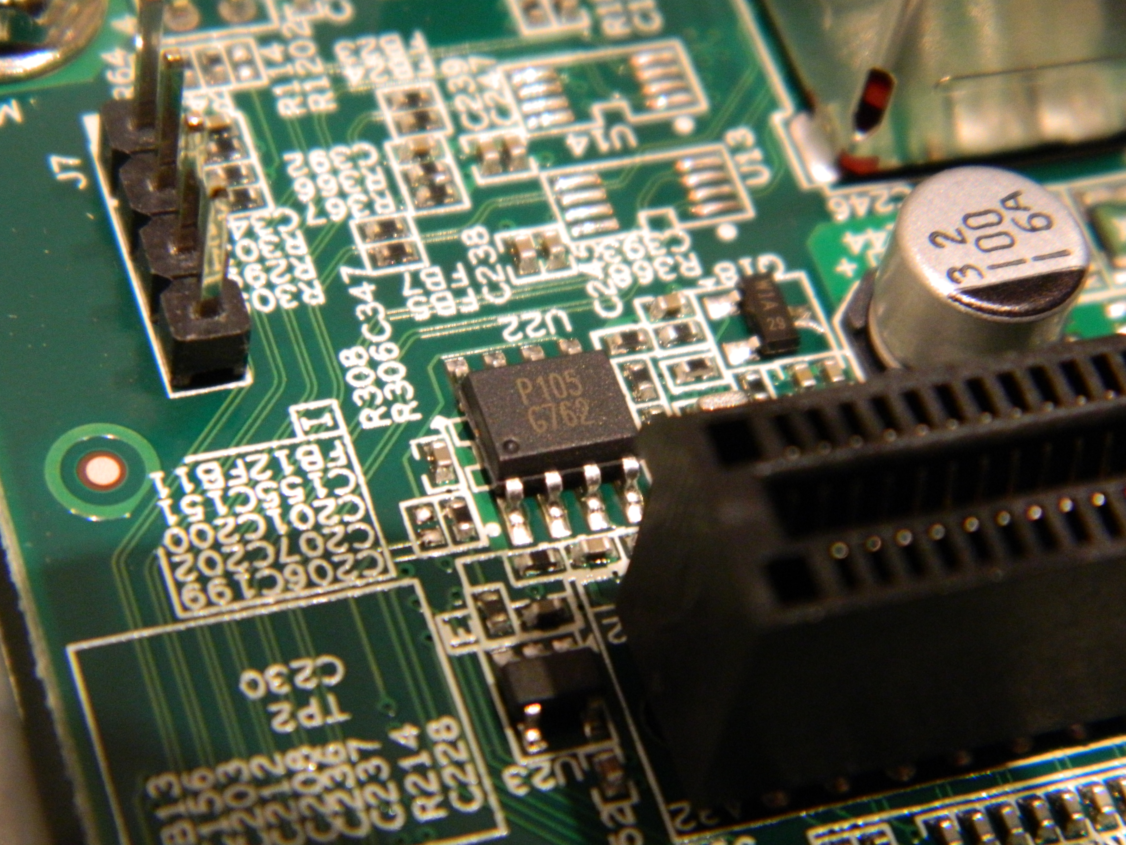
After some work, I managed to get G762 driver accepted upstream in 3.11 kernel. That been done, it can now easily be referenced in Duo v2, RN102 and RN104.
Take a look at the fancontrol section to see how the fan controller can be coupled with the temperature sensor.
Marvell 88E1318 Gigabit Ethernet PHY
The Marvell ARMADA 370 SoC comes with two integrated Ethernet MAC but does not include the required PHY. The ReadyNAS 104 has two Marvell 88E1318 Gigabit Ethernet PHY connected to the SoC via RGMII interfaces.
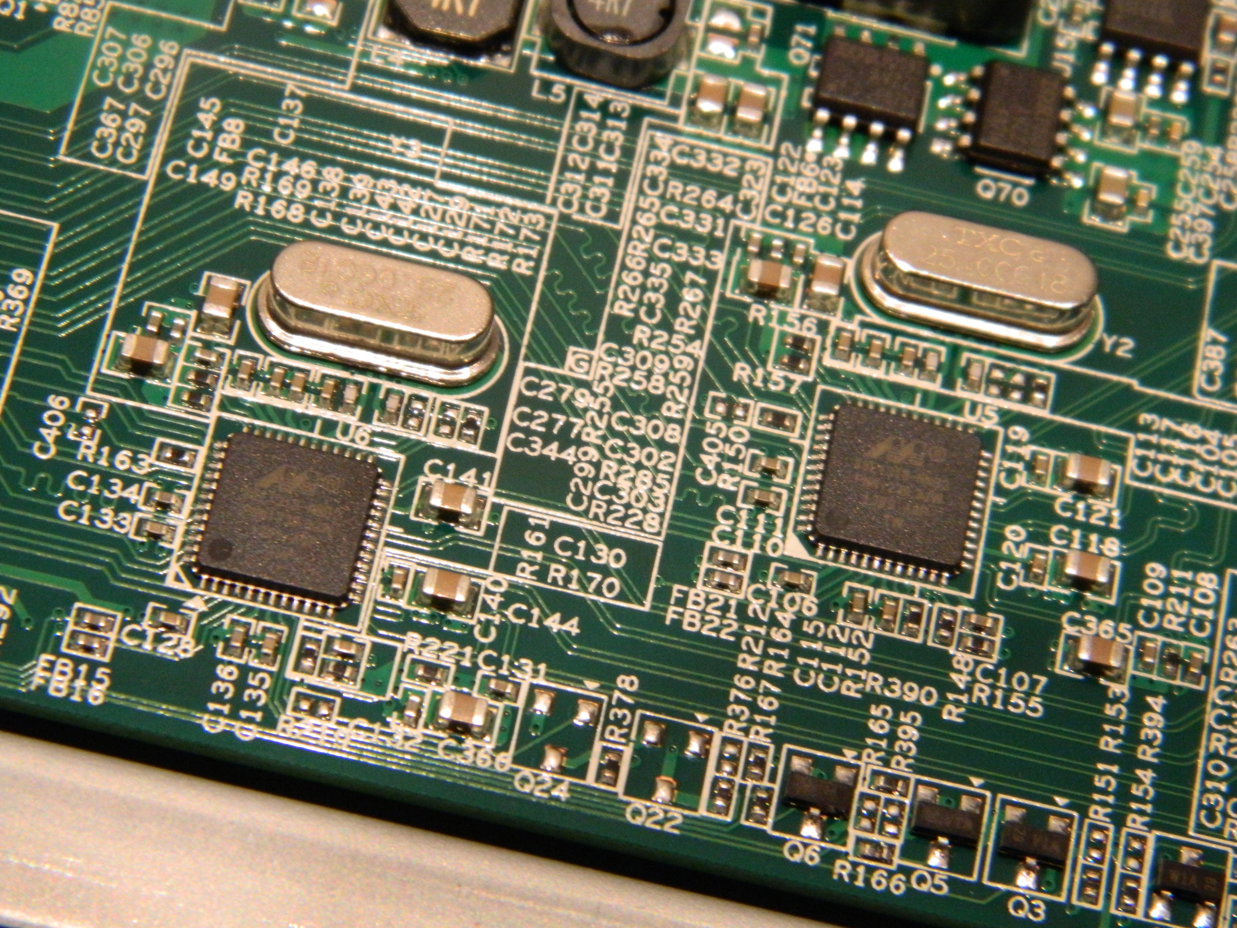
The picture below provides a closer look to the PHY chip.

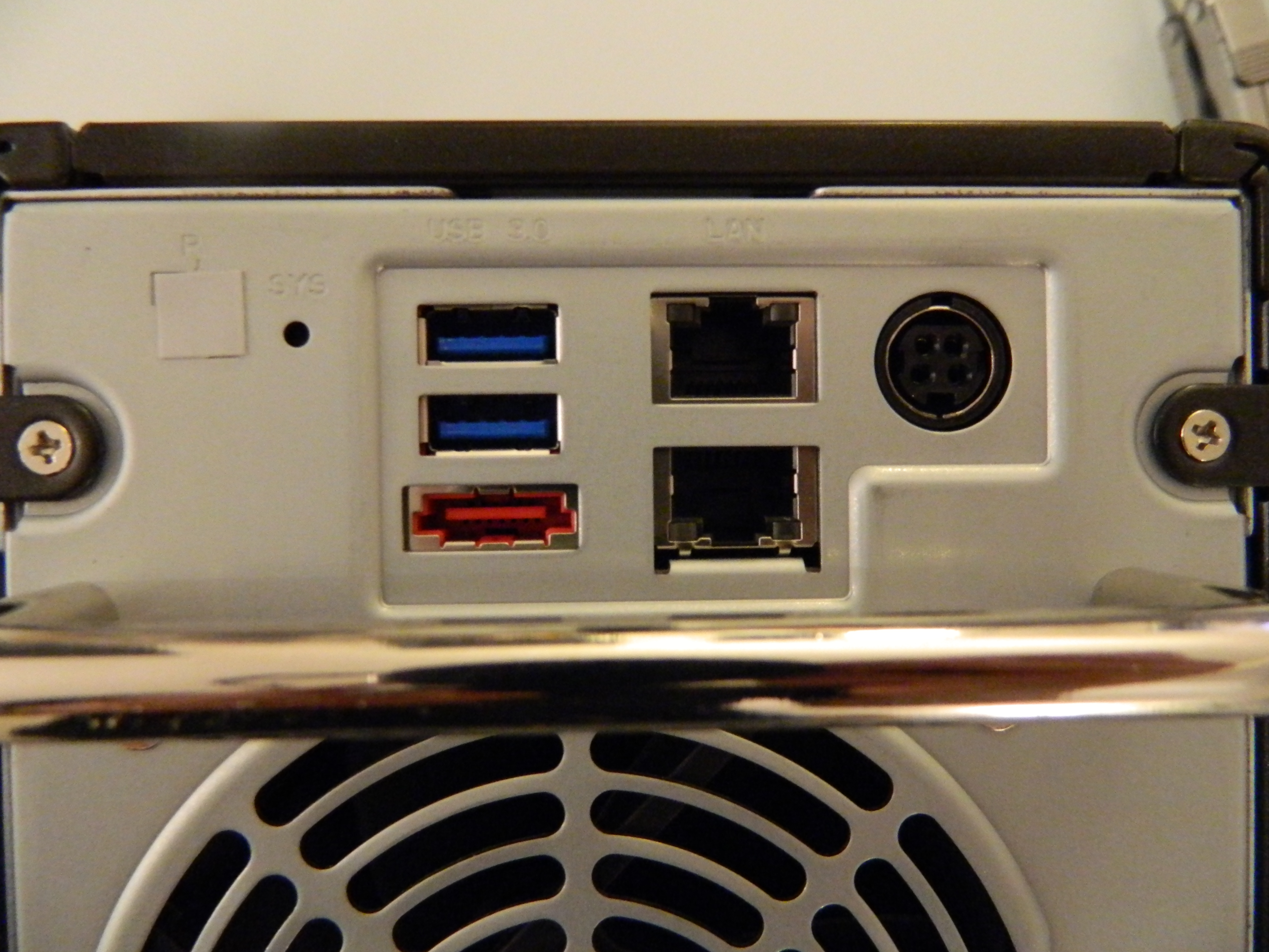
RN104 rear view
The picture provides a rear view of the NAS, including from left to right
- The sticker hiding the four pins of the UART (GND, TX, RX, VCC)
- The reset button (below the SYS indication)
- The two USB 3.0 ports (in blue) connected to the Fresco Logic FL1009 XHCI controller
- The eSATA port (in red), connected to one of the SATA interface of the SoC (i.e. not handled by the Marvell 88SE9215 SATA controller used for internal disks).
- The two GbE interfaces connected to the Marvell 88E13138 PHY connected to the SoC.
- The power connector
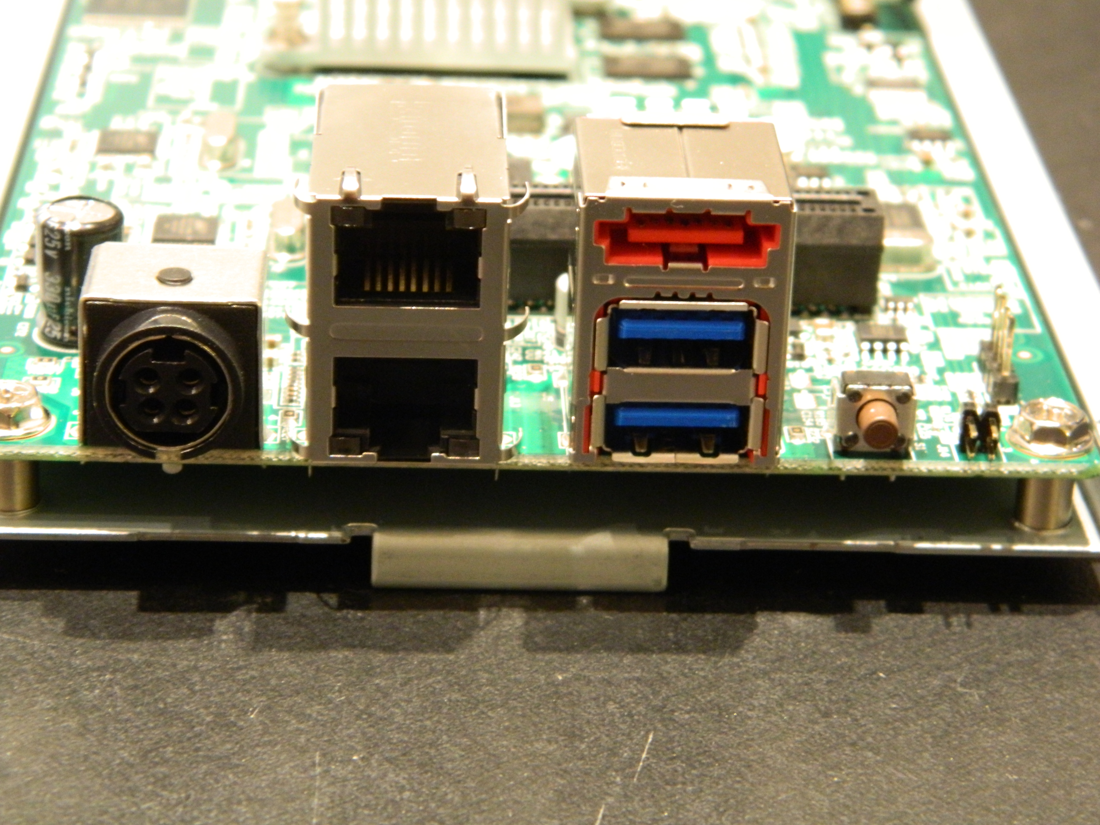
The picture below provides a view of the same interfaces, but with the case removed and a different rotation angle (NAS is upside down).
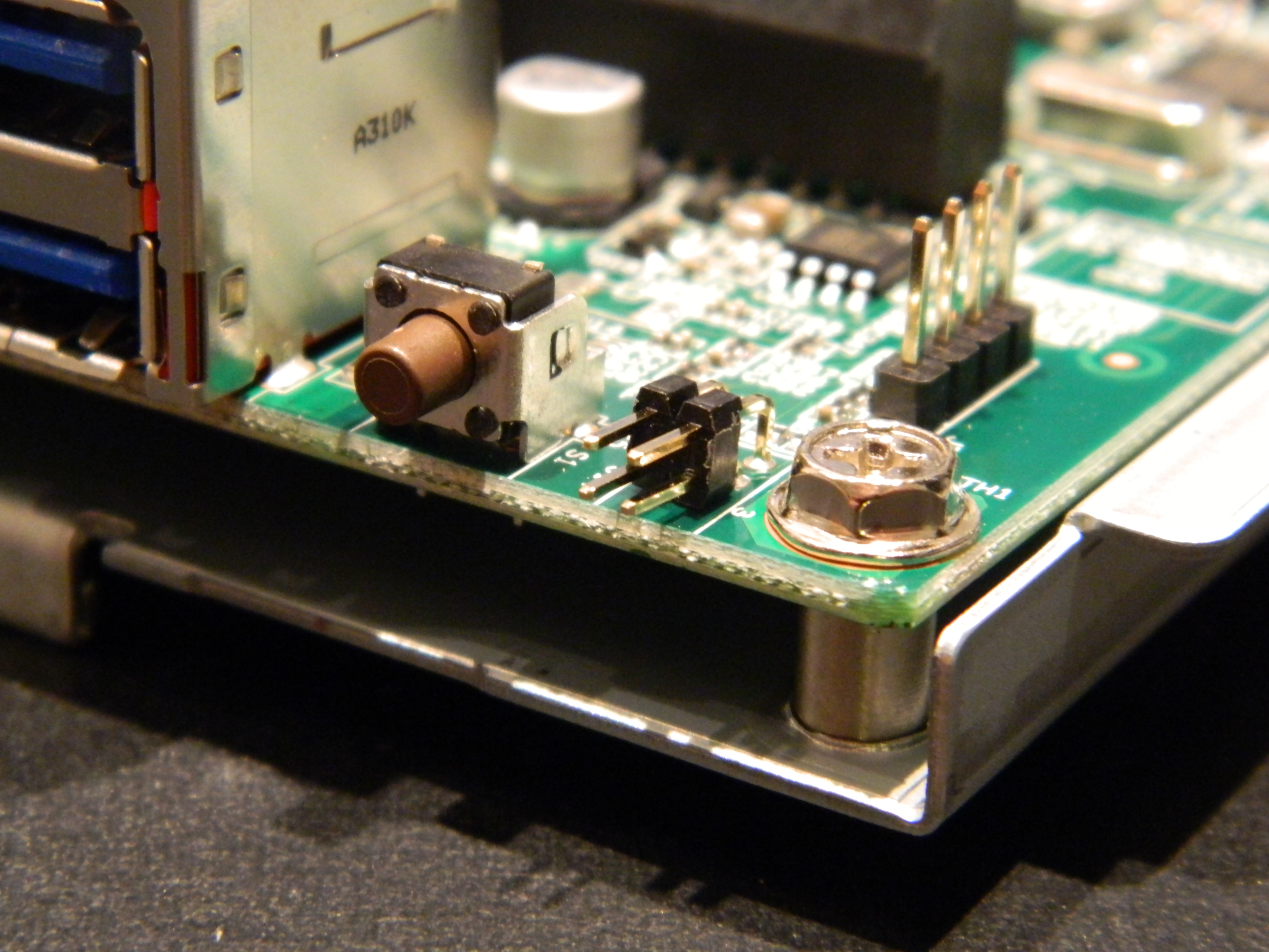
This last picture provides a closer look of the UART pins available under the sticker, near the reset button.
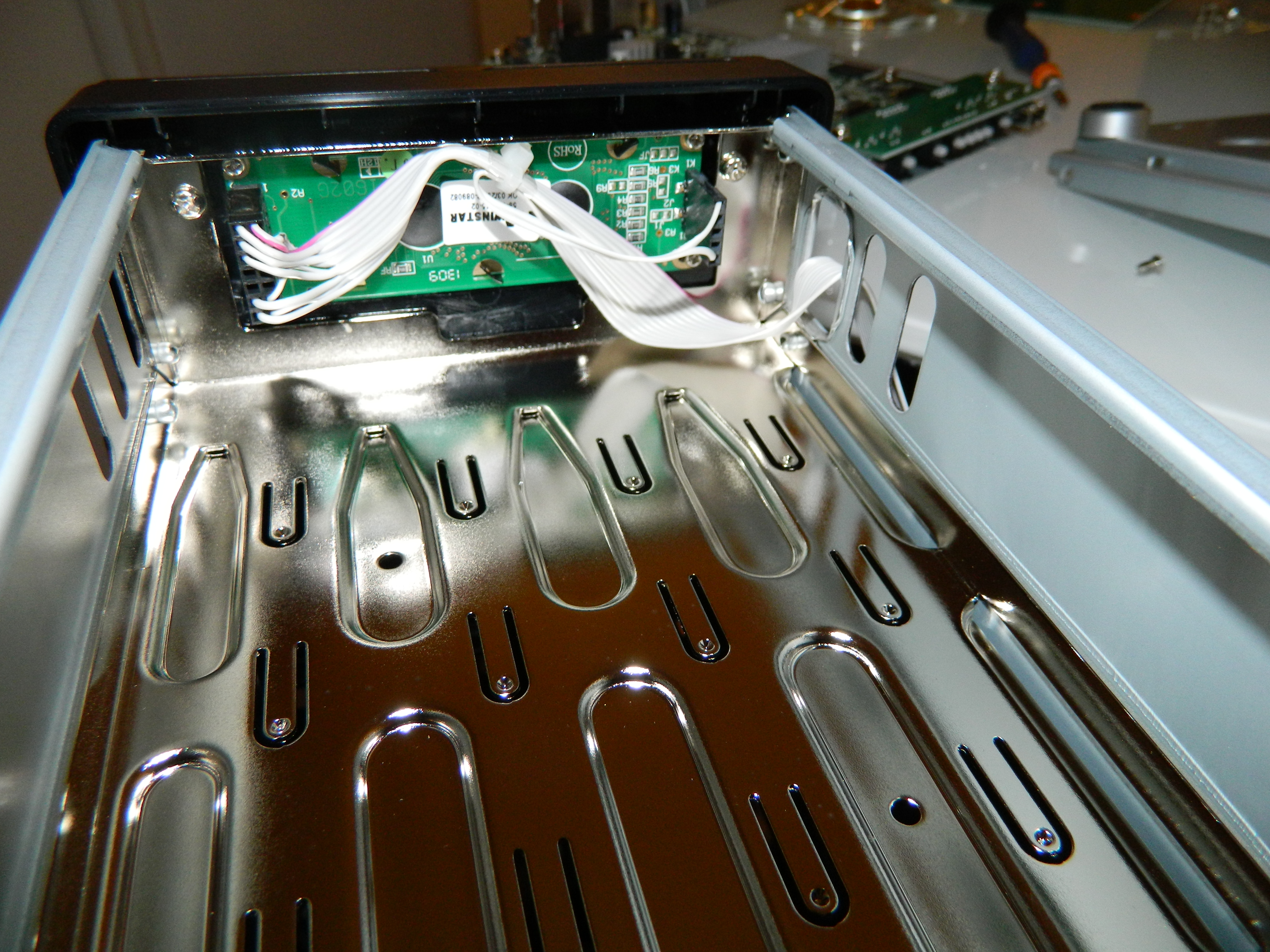
RN104 LCD module (Winstar 16x2 WH1602 LCD)
Unlike the ReadyNAS 102, the 104 comes with a 16x2 character LCD module, namely a Winstar WH1602. The LCD is located on the front of the NAS at its bottom. The picture below provides a rear view of the module (the NAS is upside down). Unlike the 102 which has no lost space internally, this also shows that the RN104 has some, which explains why it is taller than the 102.
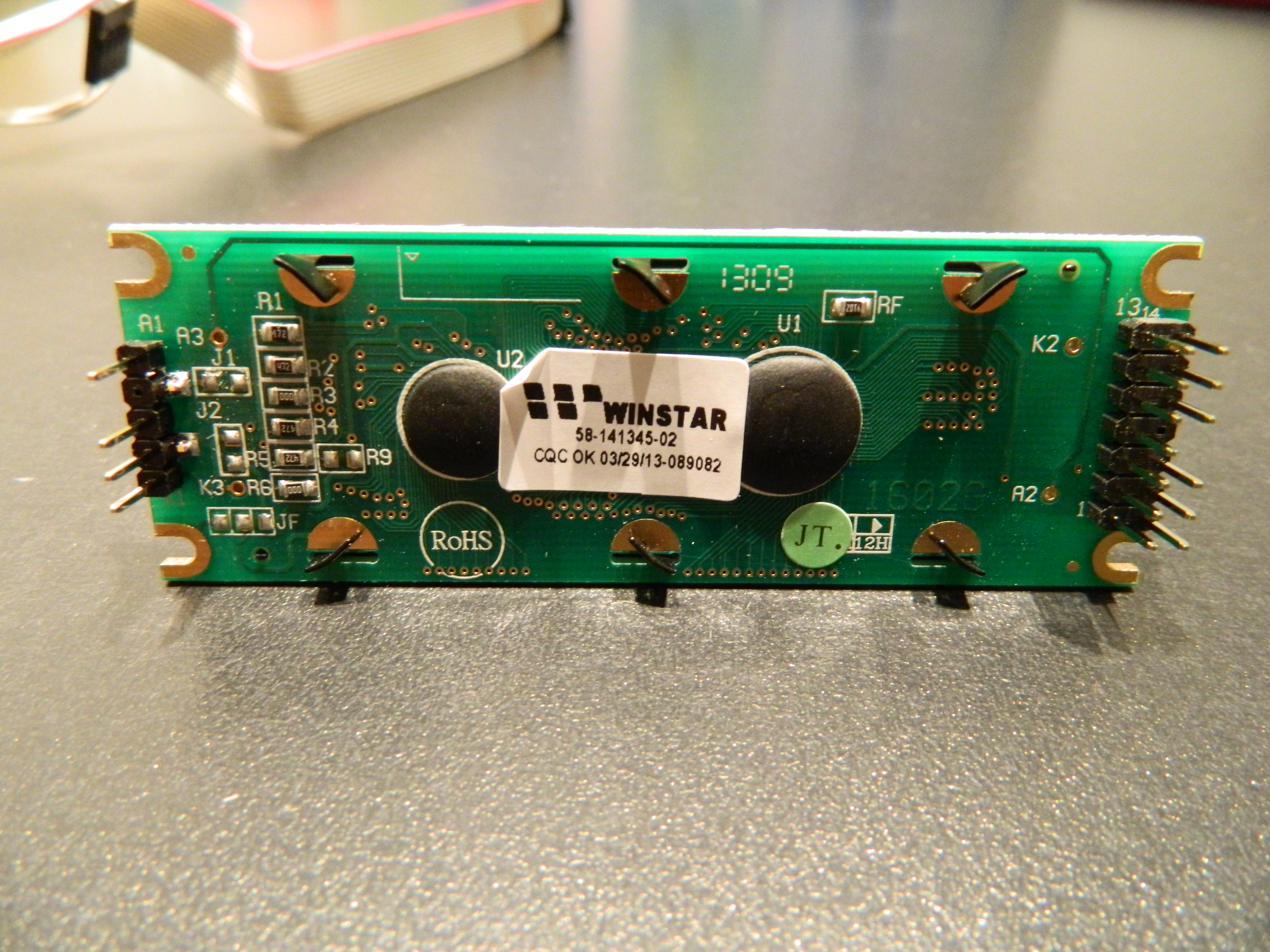
The picture below provides a view of the rear side of the LCD module, extracted from the NAS. This shows the pin of the LCD modules connected to the GPIO pins of the SoC (on the right) and the pins providing power to the LCD module (on the left).
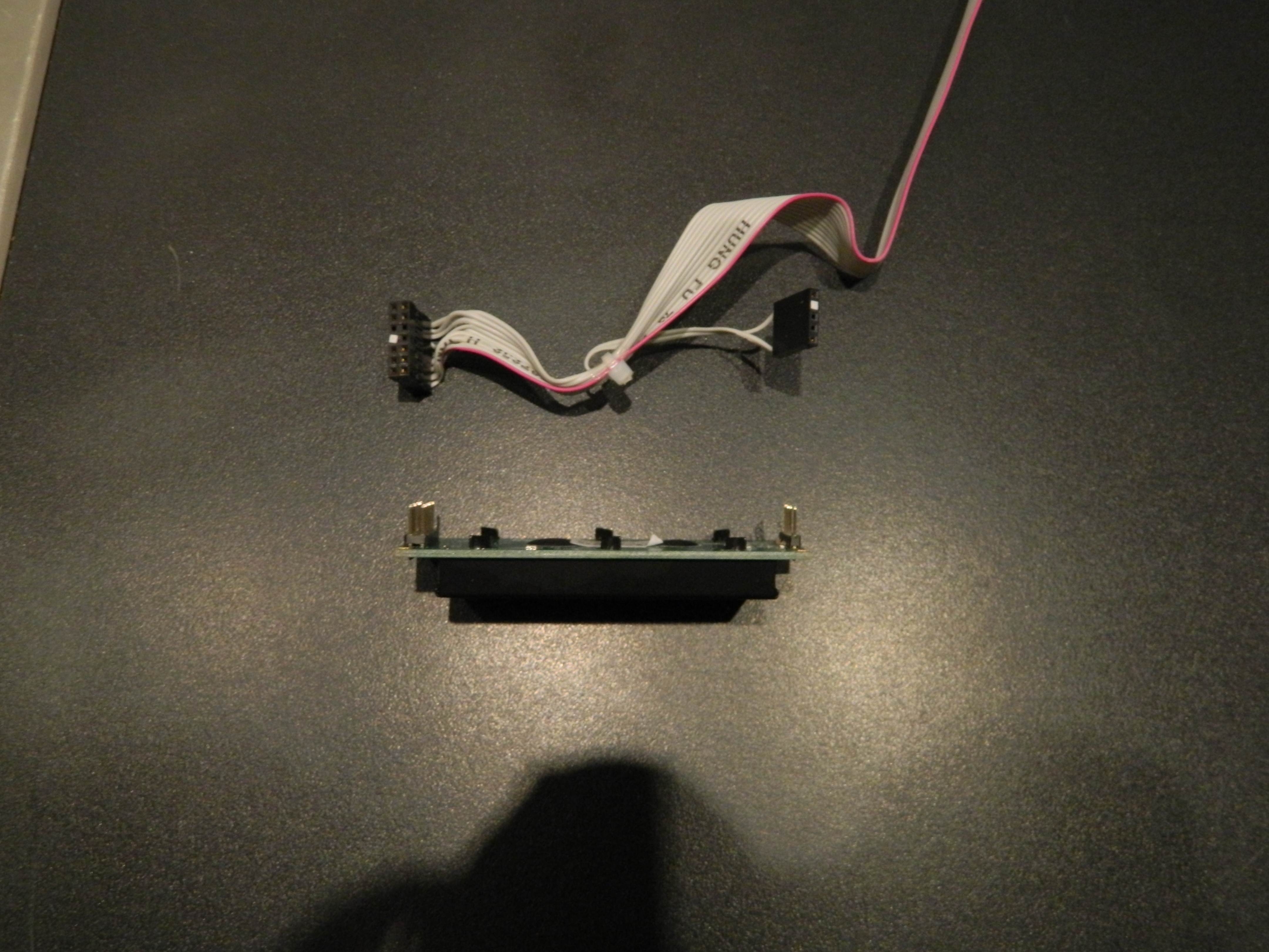
A view from the top with the cable is given below.
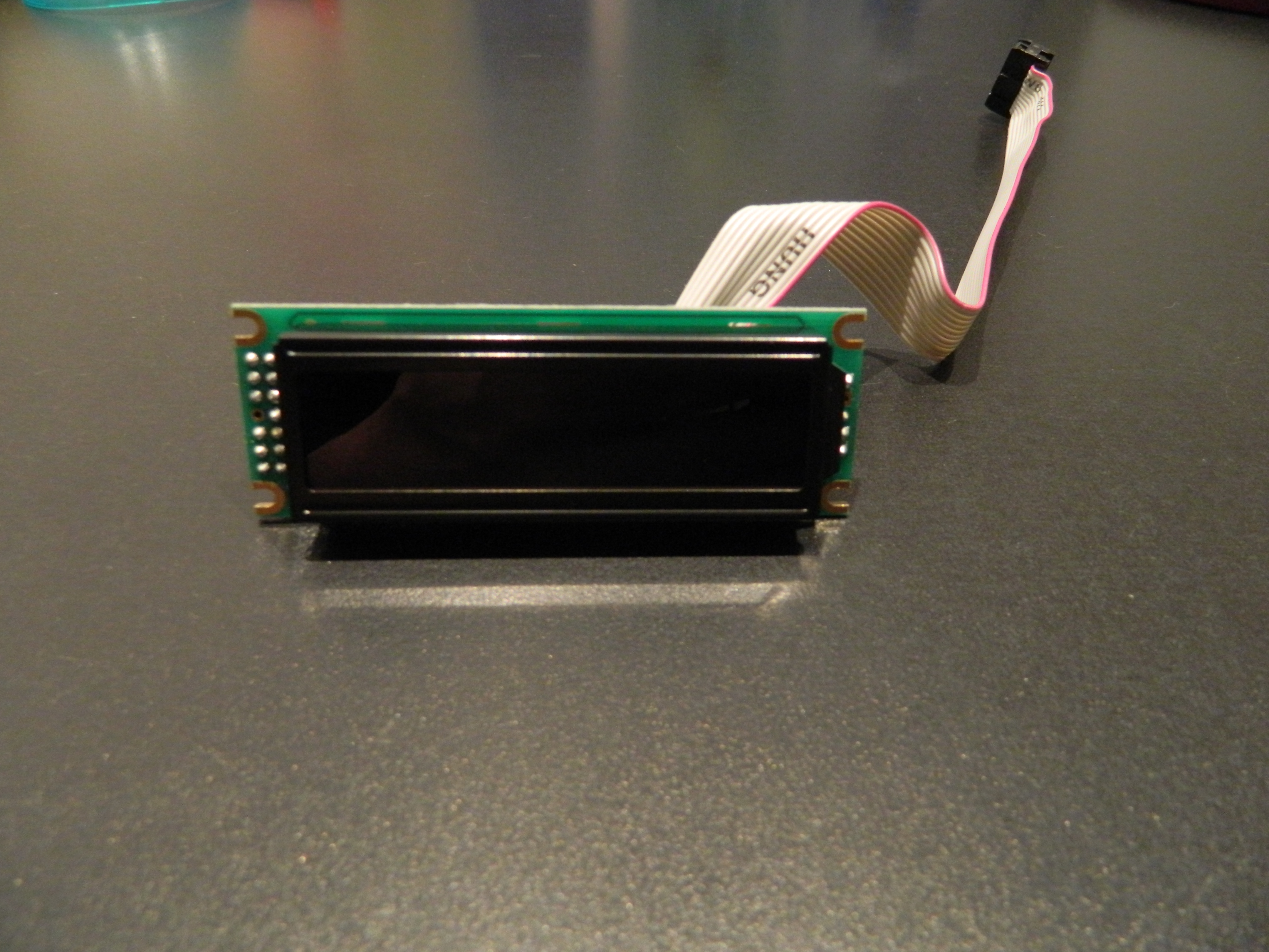
A front view of the LCD module is given below.
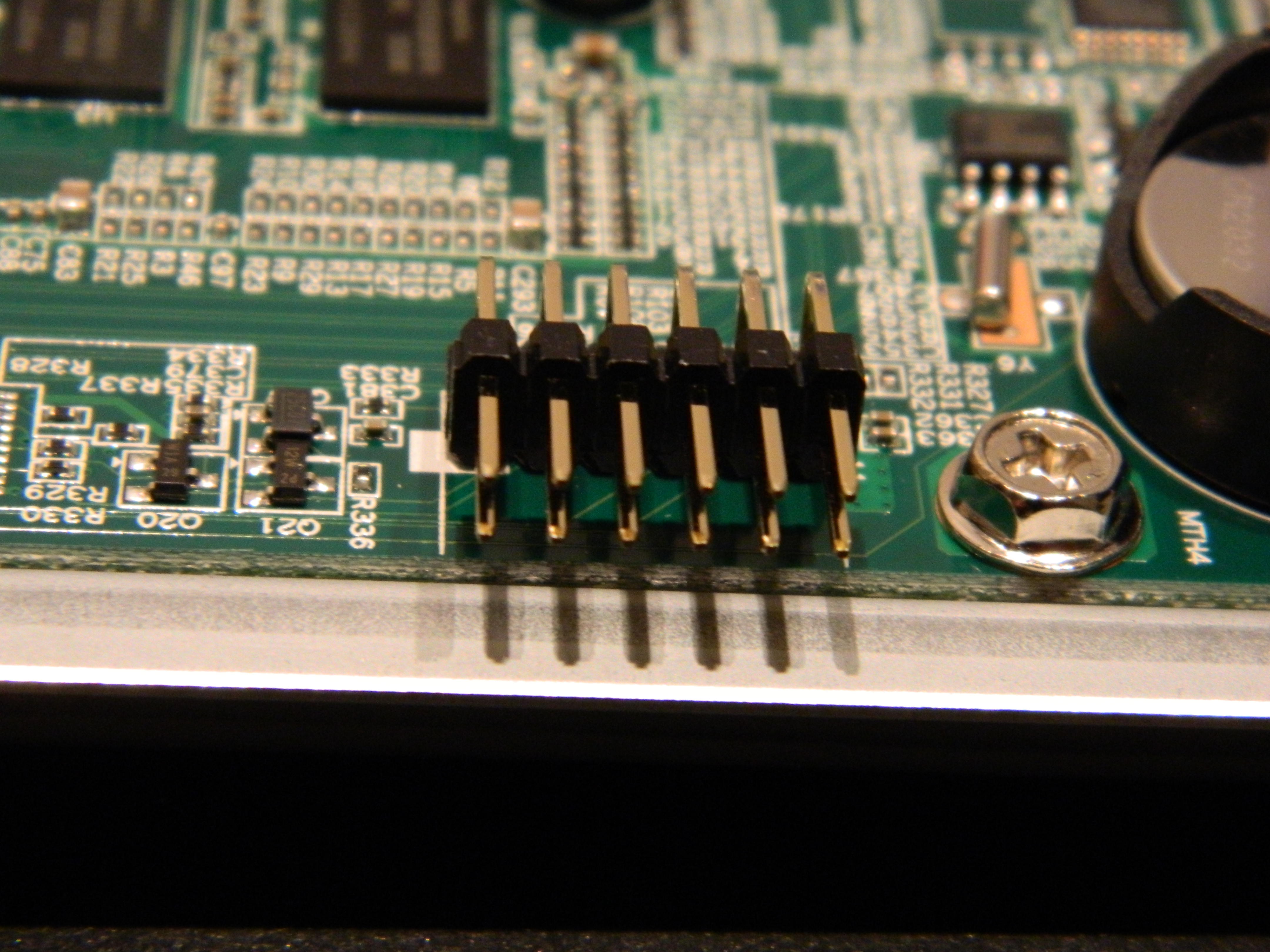
The pins on the main board of the NAS to which the LCD module cable is connected are presented below.
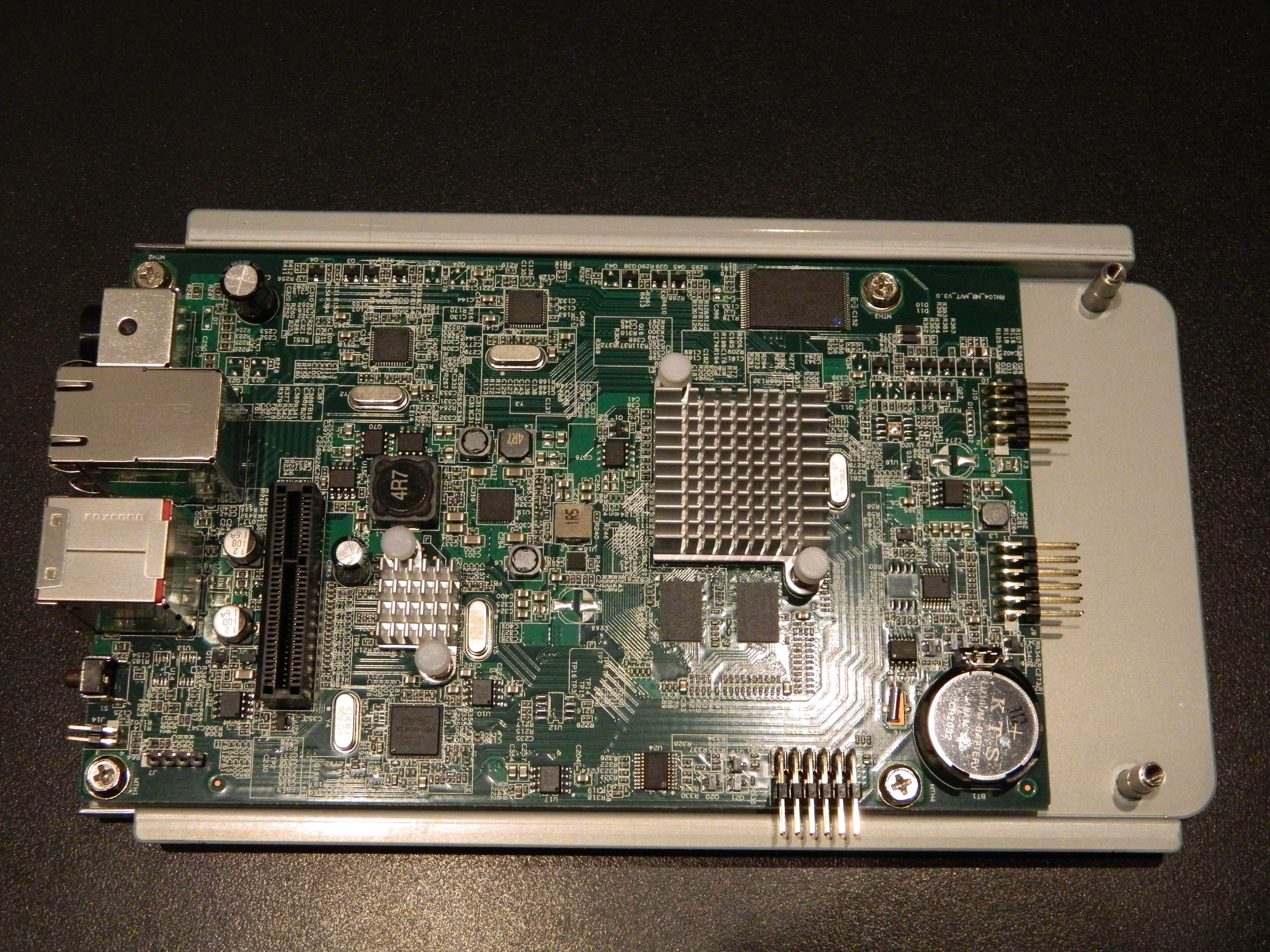
RN104 main motherboard
The picture below provides a view of the main board. The SATA extension board is not conected. The associated connector is the back one on the left near the USB and GbE ports. The small heatsink on the left is the one dedicated to the Marvell 88SE9170 SATA controller. The picture does not present the daughter board providing the front LED and buttons (presented in next section).
Main daughter board (USB 2.0, LEDs and buttons)
The daughter board providing the front LEDs, the front USB 2.0 port (connected to the SoC) and the backup and power buttons is depicted below:

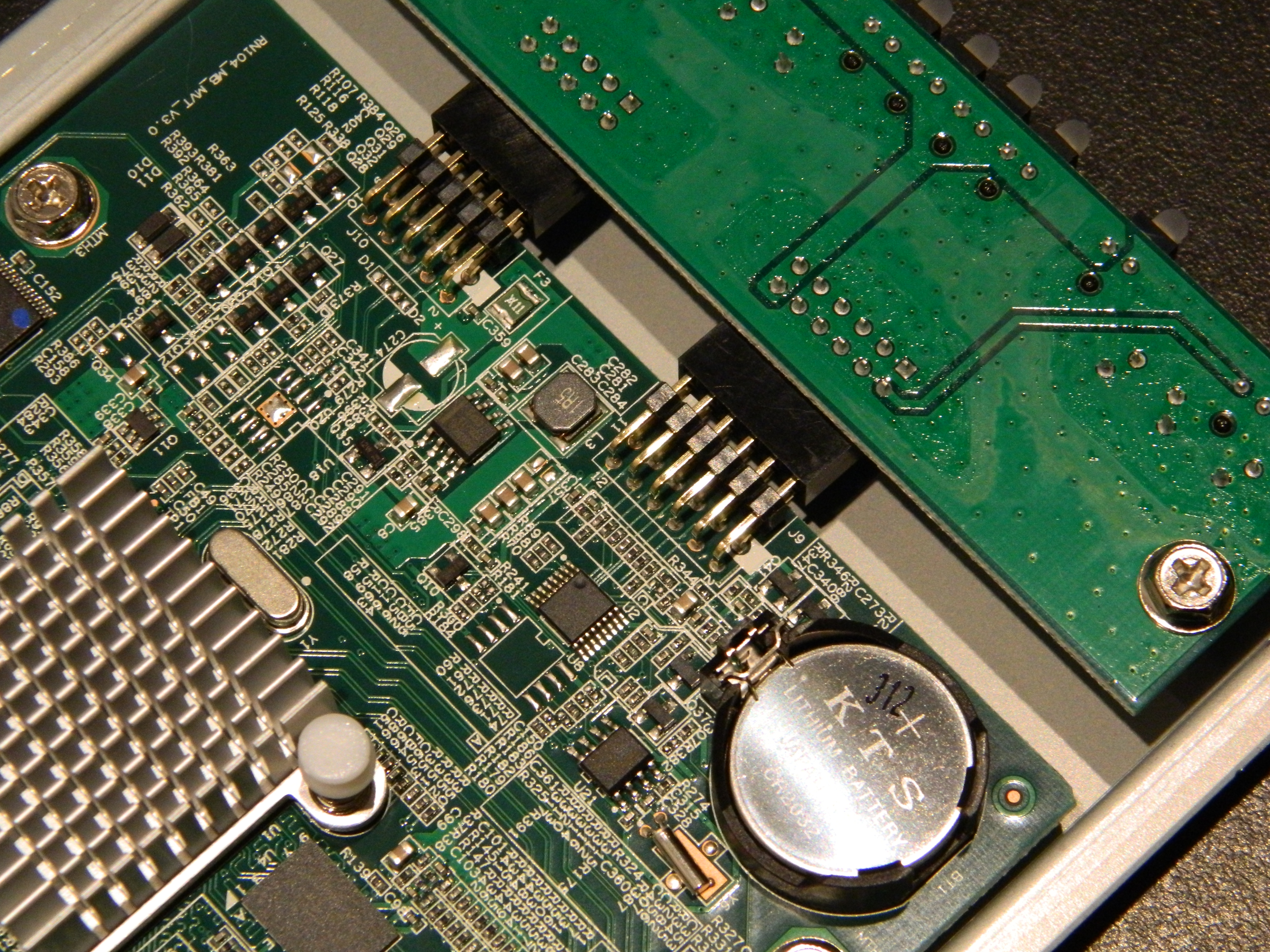
The connection of the daughter board to the main board is given below.
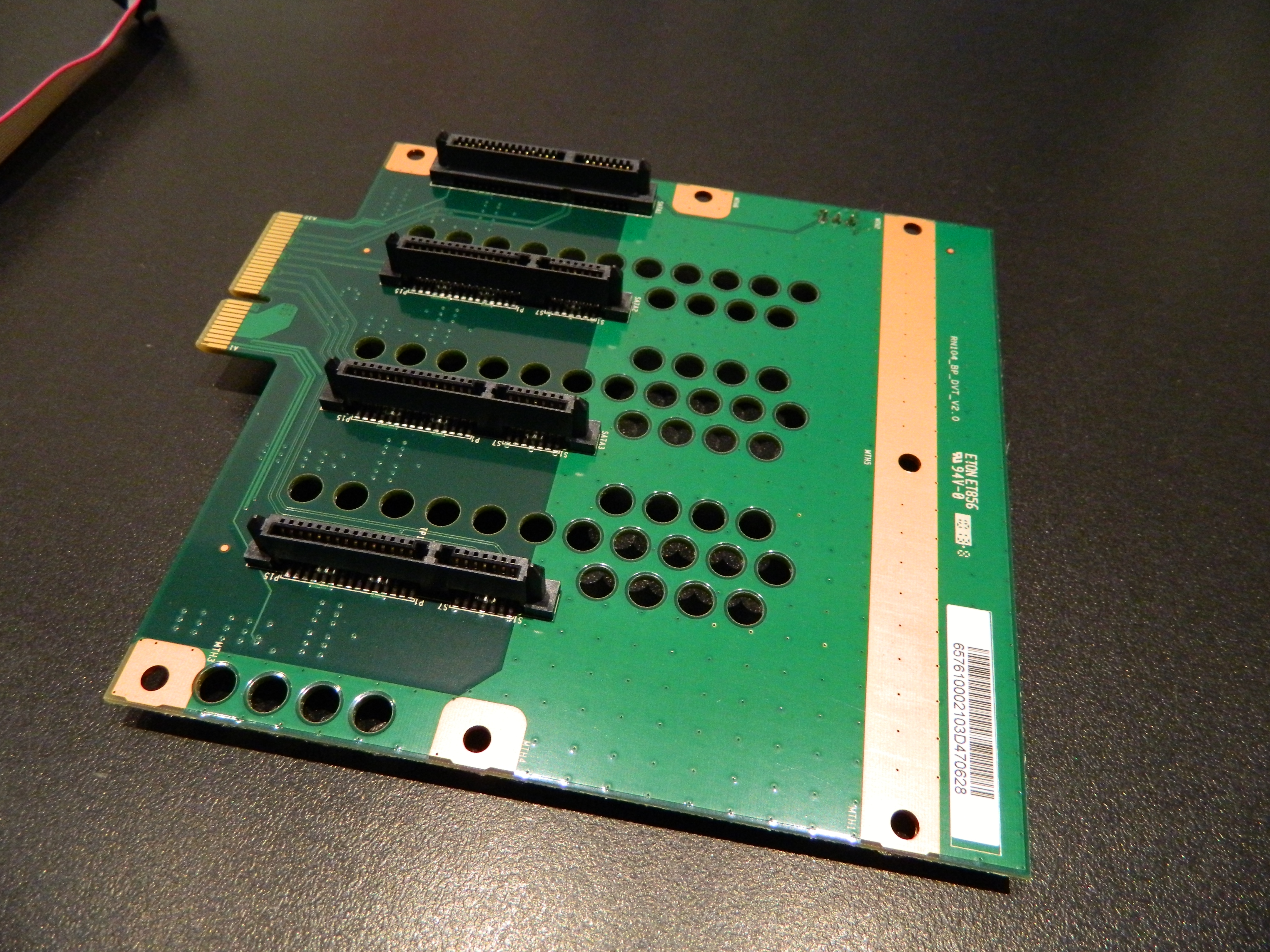
SATA expansion board
The SATA expansion board to which the disks are connected is depicted below.
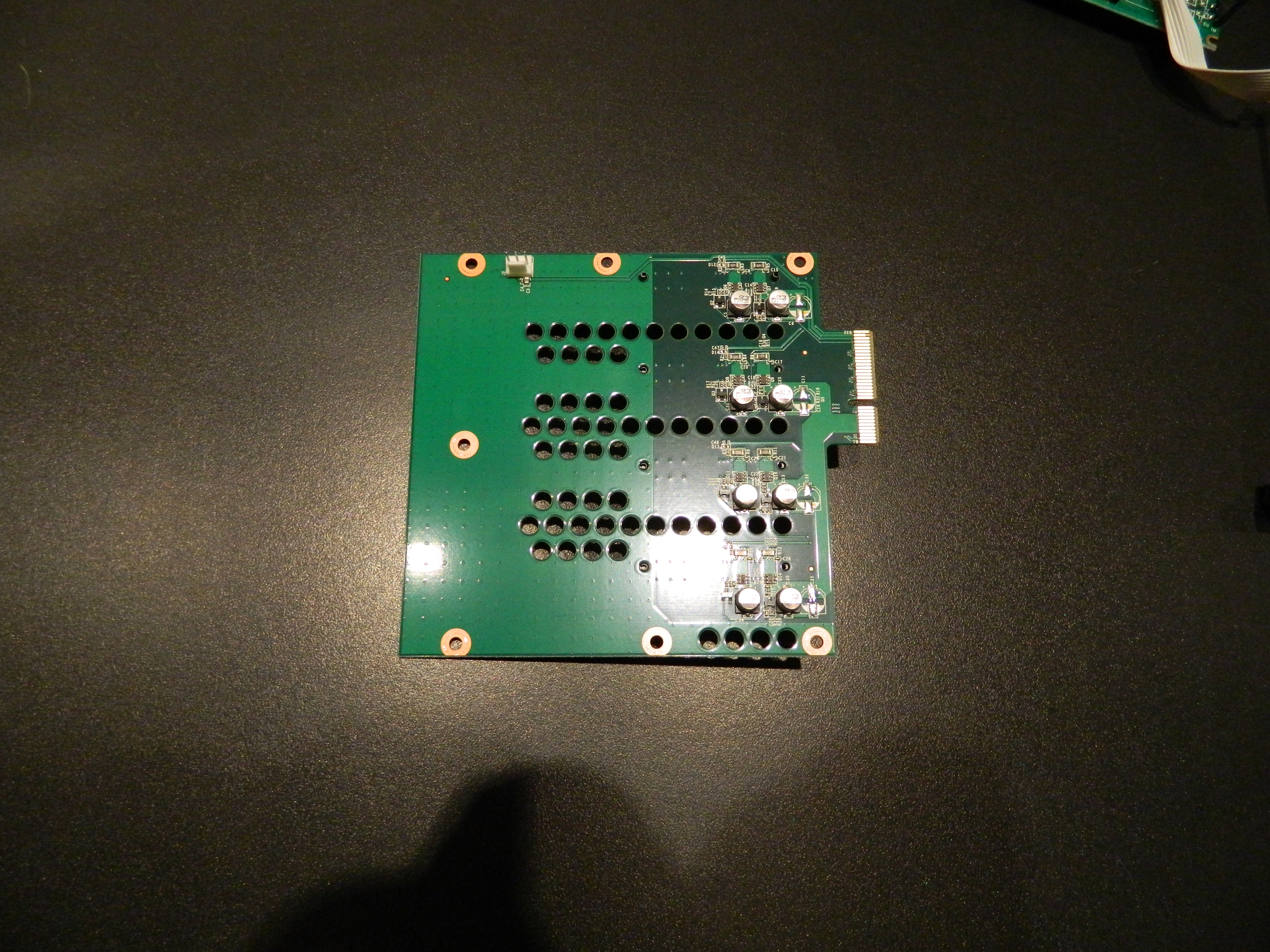
The rear of that board is depicted below.
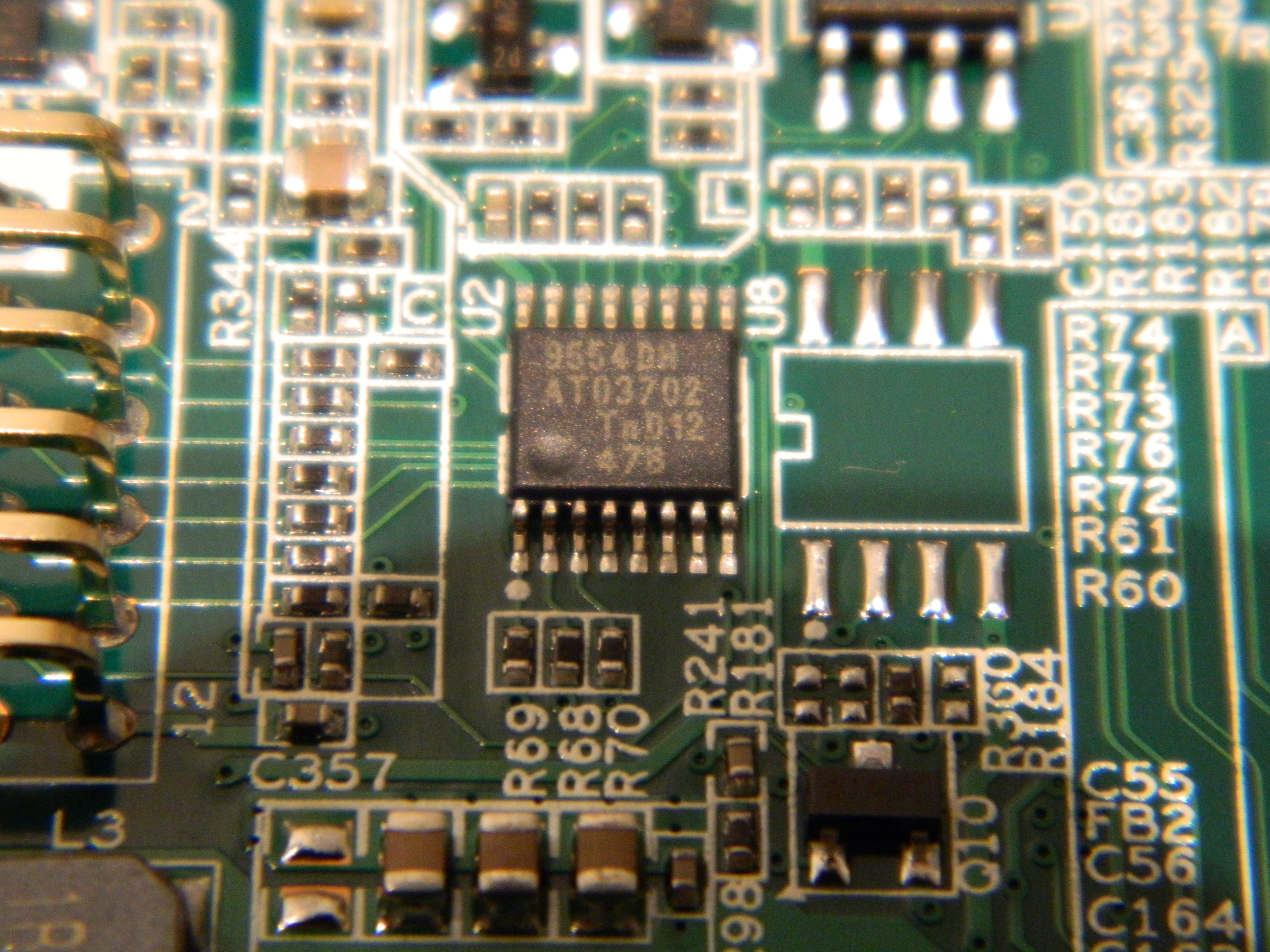
NXP PCA9554
The LCD module consumes 8 GPIO of the SoC. In order to get additional GPIOs to connect to front buttons and LEDs, NETGEAR has added on the main board an iomuxer connected to the I2C bus, namely a NXP PCA9554. It provides eight additional GPIOs. The picture below provides a top view of the component. It is located near the pins used to connect the main board to the front daughter board.
Local copy of NXP PCA9554 datasheet.
Richtek RT8105

Local copy of Richtek RT8105 datasheet.
TI TPS54227
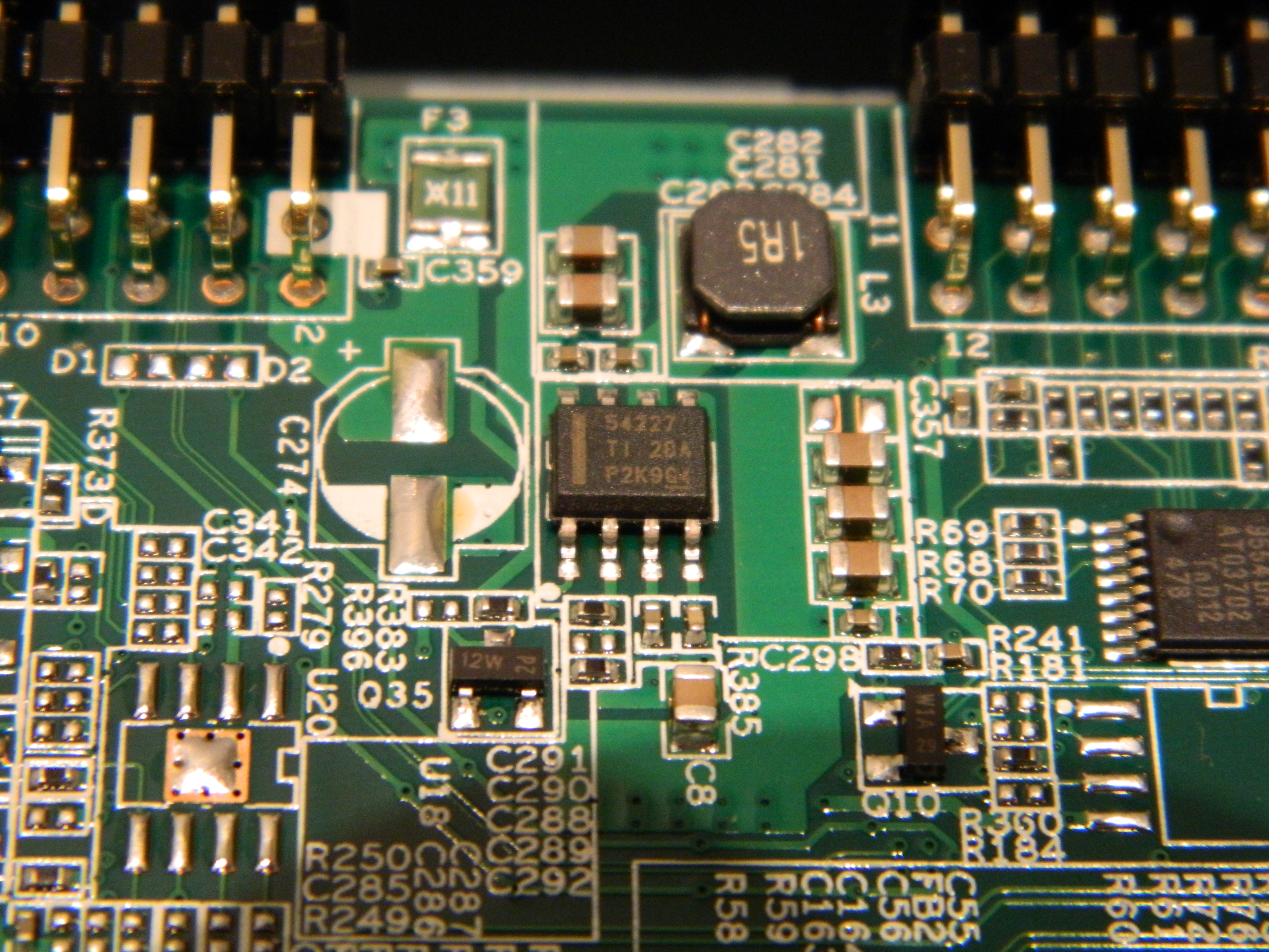
Local copy of TI TPS54227 datasheet.
TI TPS65251
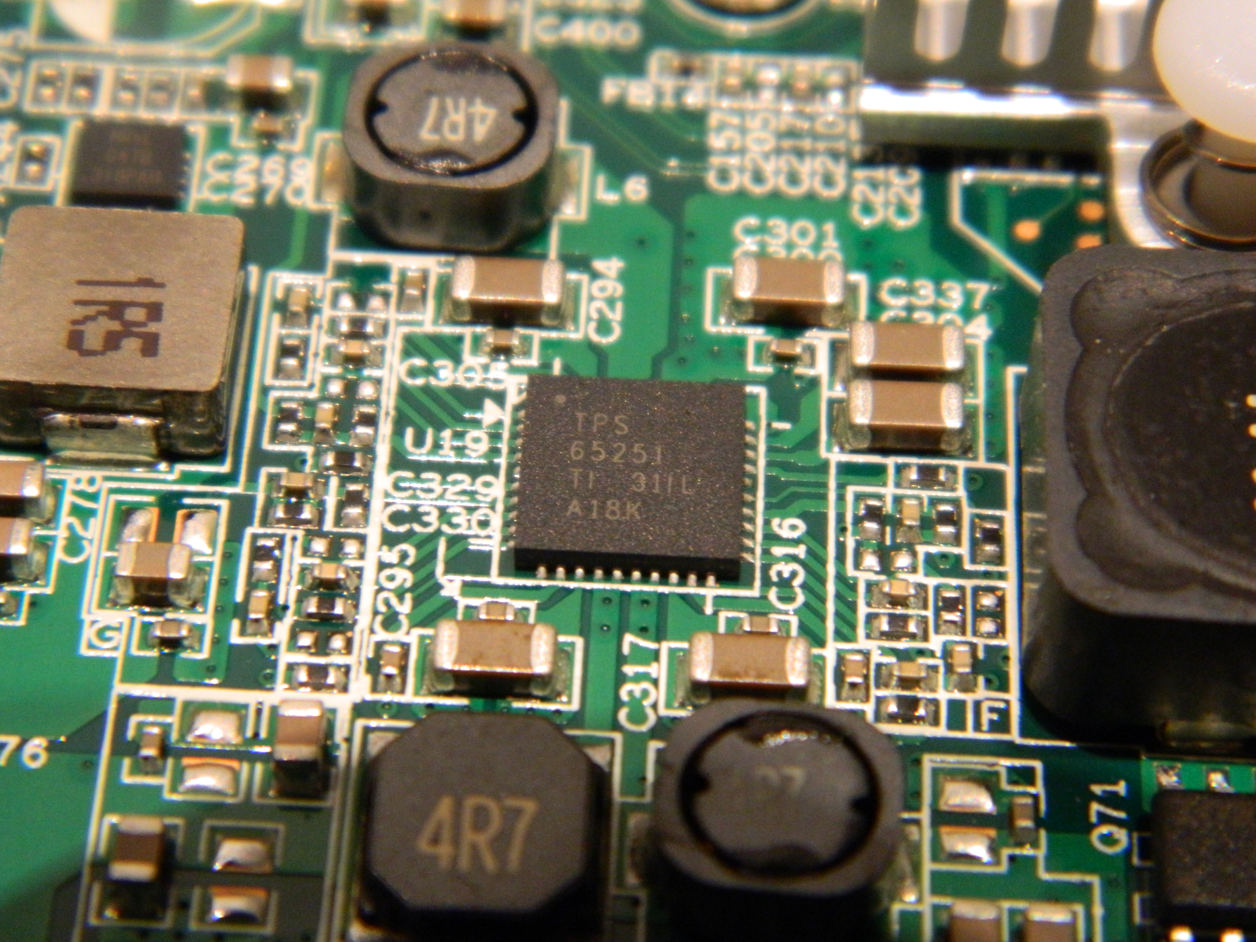
Local copy of TPS 65251 datasheet.
NXP LVC244A
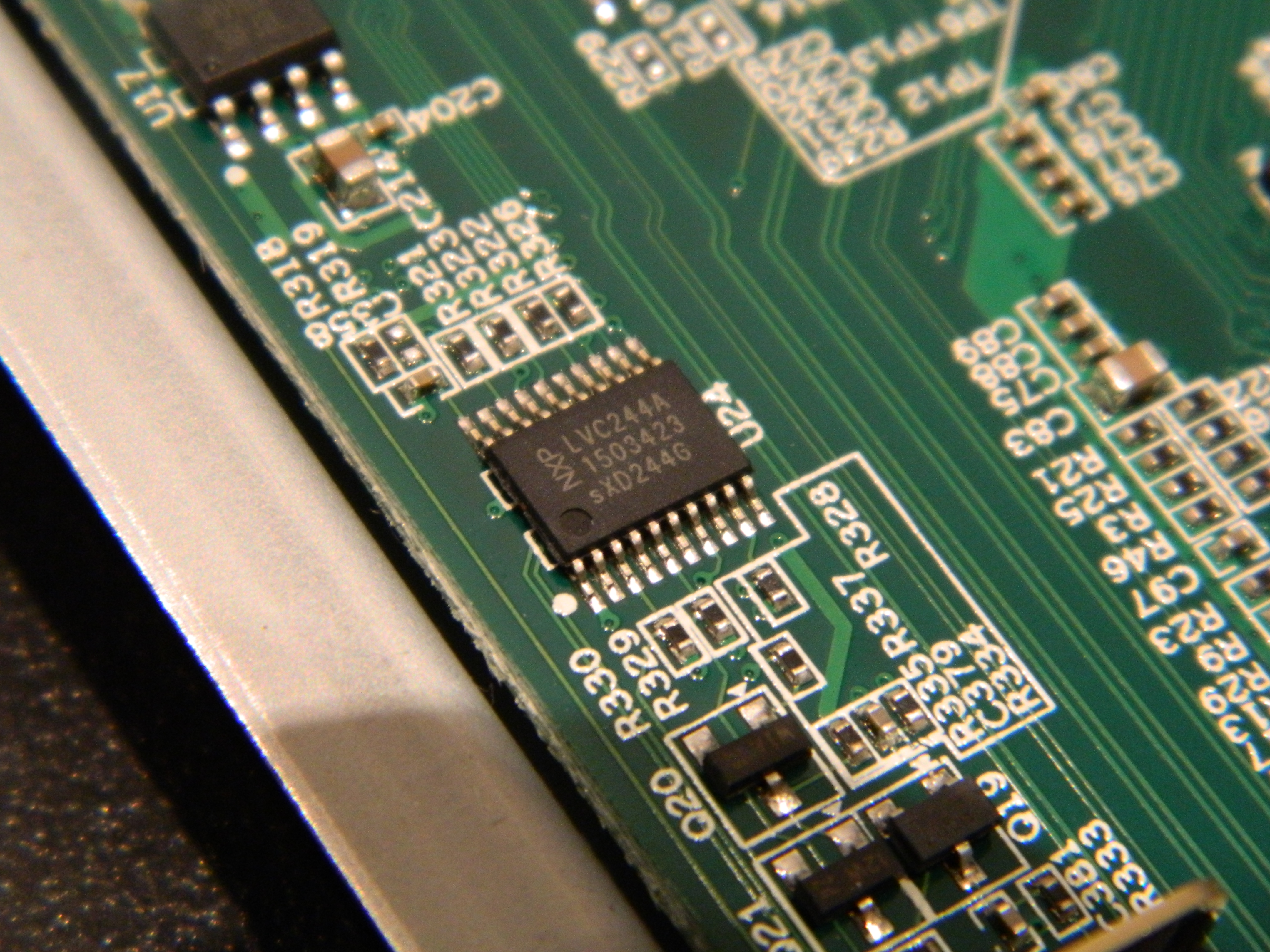
Local copy of NXP LVC244A .
Configuring custom actions for buttons
If you want to trigger custom actions using the power, backup and reset buttons, you can probably use this script as a basis.
Configuring alarm for poweroff and automatic reboot
Alarm IRQ pin (IRQ#2) of ISL12057 RTC chip is not directly connected to the SoC on RN102, RN104 and RN2120, but to a PMIC (TPS65251), handling powering of the device. The PMIC does not provide a way to report the status of the IRQ#2 pin. This is not a common design pattern on Linux and requires some specific kernel adaptation. This is the reason why alarm support (1a67e256dbd8, 298ff0122ab1, fd71493d6797) for those NAS took a bit longer than expected. If you are interested by the details, the commit messages and the code provides more information.
As also documented in alarm support commits, using the alarm feature now available on the device is very simple. Here is a straightforward example of how this can be done:
# echo `date '+%s' -d '+ 1 minutes'` > /sys/class/rtc/rtc0/wakealarm
# shutdown -h now
After having configured the alarm one minute in the future, and then having powered off the system, you should see it come back to life after a minute. Now, if you want to poweroff the device each night and have it come back say in the morning or in the afternoon, you simply need to create a crontab. This is left as an exercise for the reader.